Complete ModelSolid User Manual
English edition · Repository review: 21 September 2026
This manual explains how to use ModelSolid from your first login to generating a product: prepare models, capture parameters, define rules, build the form, publish the project and retrieve its results. It includes procedures for customers, sales teams, authors and administrators.
The reference is the code in this repository revision. Some buttons may still appear in Spanish; their original labels are included where useful. Examples are for learning and are not manufacturing specifications.
This public edition explains the application workflow. For installation-specific addresses and paths, contact your administrator.
Contents
- What ModelSolid does
- Which tools you need for your role
- Installation and first login
- Quick guide for customers and sales teams
- Essential concepts
- Workspaces and projects
- Preparing engineering models
- Capturing models in SOLIDWORKS®
- Defining variables
- Creating and testing rules
- Features, properties and replacements
- Building the web form
- Publishing and updating
- Choosing output files
- Templates and documents
- History and jobs
- Users, roles and permissions
- Lookup tables
- Worker and Autopilot
- Complete tutorial: configurable plate
- Maintenance and changes
- Troubleshooting
- Checklists
- Frequently asked questions
- Glossary
- Installation details and support
1. What ModelSolid does
ModelSolid turns a parametric model into a configurable product. An engineer prepares a part or assembly; an author defines which values users can choose and how they affect the product; a user fills in a form; the generation process opens the models and produces the requested files.
For example, a company can offer a plate with variable width, height and thickness. A customer enters 300, 200 and 8 millimetres. ModelSolid calculates derived values, evaluates the rules connecting those inputs to dimensions and assigns generation to the worker.
The results depend on what the project has been prepared to produce: parts, assemblies, drawings, CAD exports and commercial or technical documents. Selecting an output does not itself create the master needed to produce it.
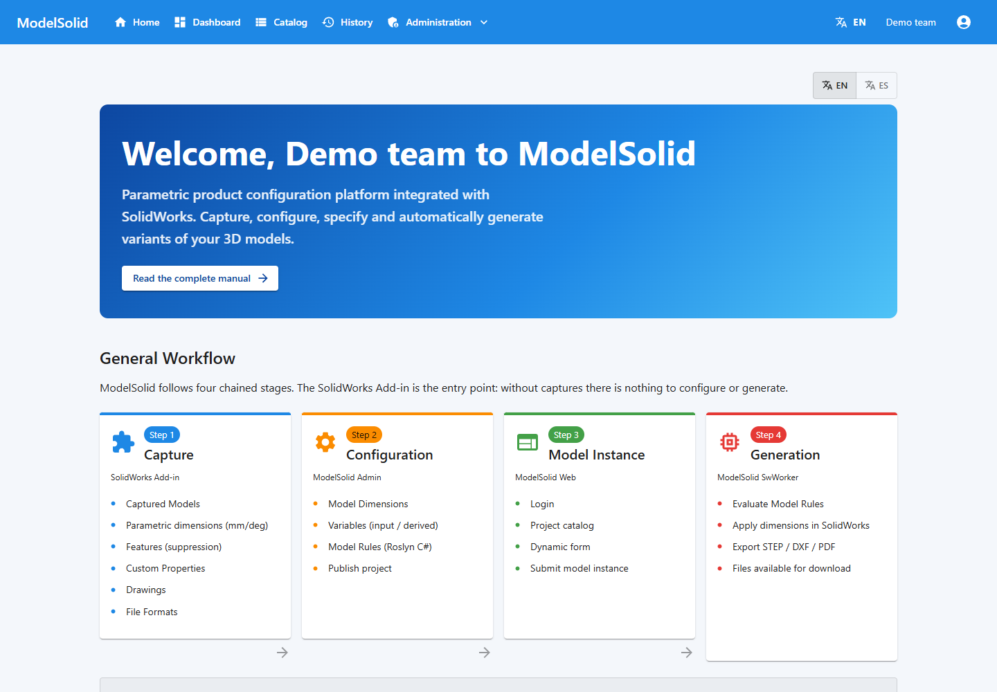
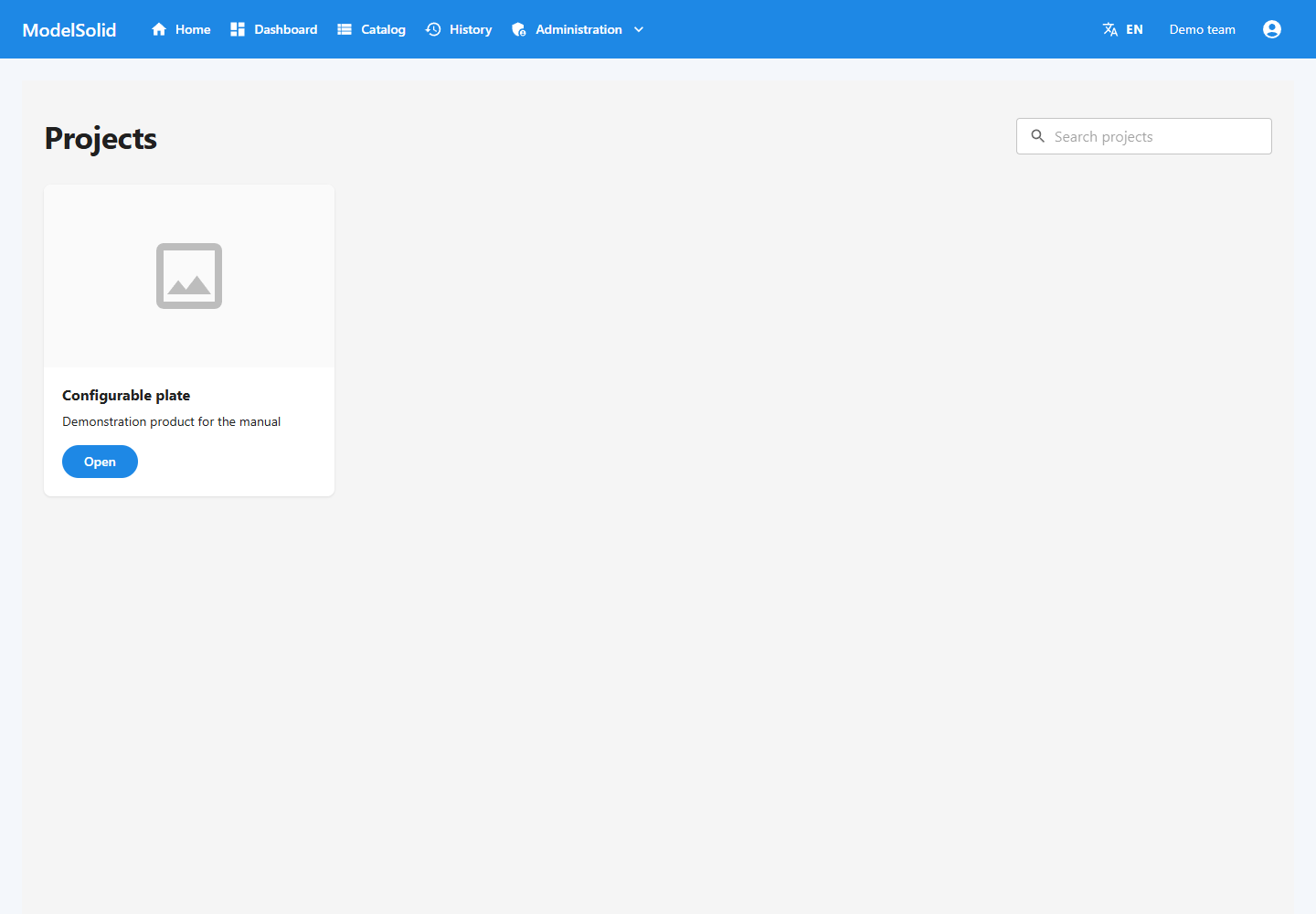
Home: entry points to ModelSolid features. Portal screenshot with demonstration data. Click to enlarge.
1.1 The journey of a request
Engineering prepares the master model
                 ↓
Capture records dimensions, features and properties
                 ↓
Admin defines variables, rules and outputs
                 ↓
The author prepares and uploads the web form
                 ↓
The administrator publishes the project
                 ↓
The user fills in the configurator and submits values
                 ↓
The API validates and calculates; creates a generation job
                 ↓
The worker uses SOLIDWORKS to generate the files
                 ↓
The user checks the result in History
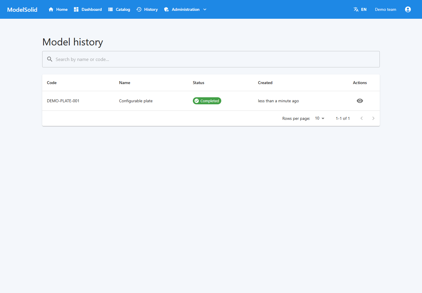
History for locating the request by code and status. Demonstration data. Click to enlarge.
1.2 Form, rules and geometry
These are separate parts of the same product. A checkbox can look correct without changing the model if its variable or rule is missing. A rule can calculate correctly but fail during rebuild if the geometry cannot support that value.
Final verification therefore includes a real generation run and inspection of its files.
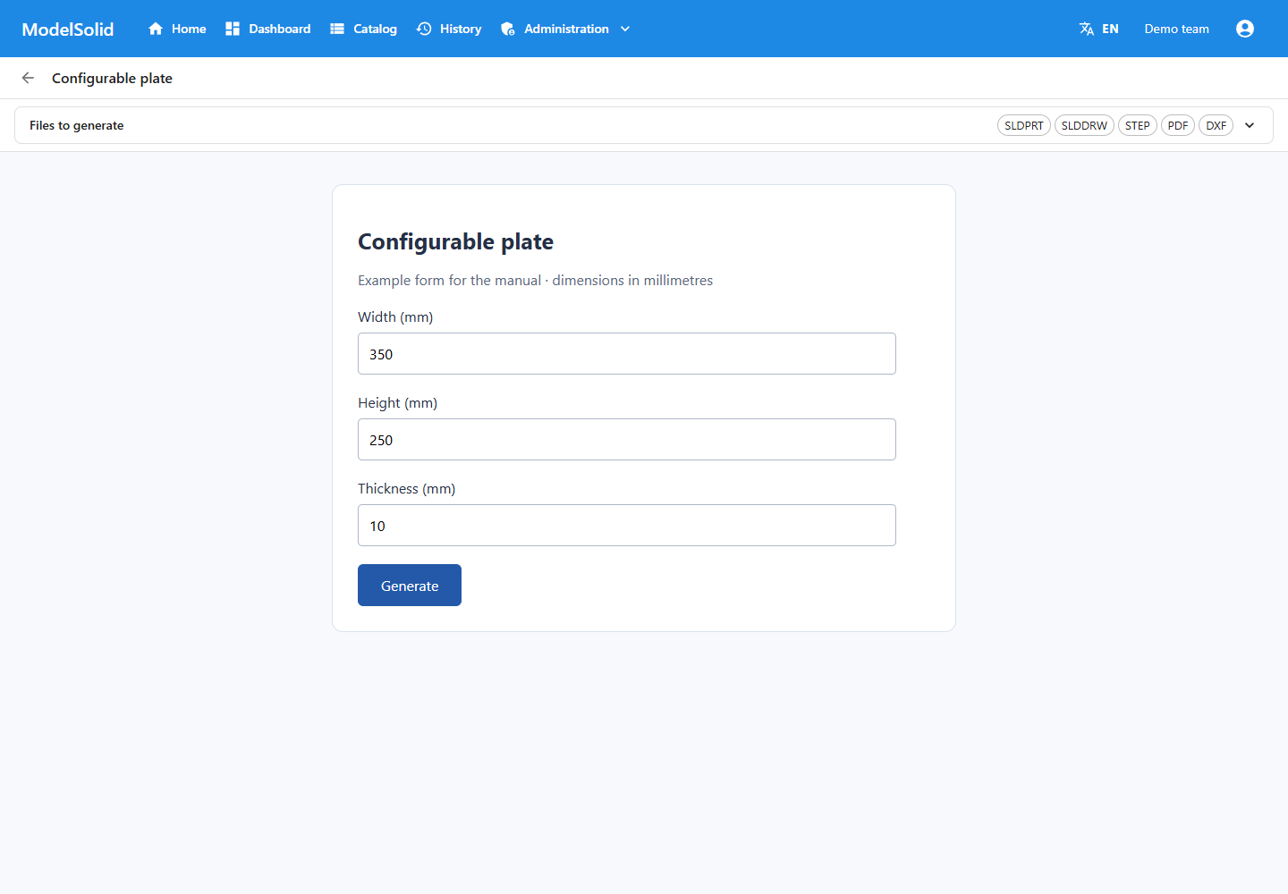
Example form with request inputs and options. Demonstration data. Click to enlarge.
2. Which tools you need for your role
| Your task | Main tool | Reading |
|---|---|---|
| Request variants | Web portal | Chapter 4 |
| Prepare geometry | SOLIDWORKS + Capture | Chapters 7 and 8 |
| Define parameters and calculations | Desktop Admin and web administration | Chapters 9 to 11 |
| Design the form | VSCode, TypeScript and CLI | Chapter 12 |
| Manage access | Administration | Chapter 17 |
| Keep generation running | Worker and Windows workstation | Chapter 19 |
These are working responsibilities, not five access roles. The usual assignable roles are Admin and User.
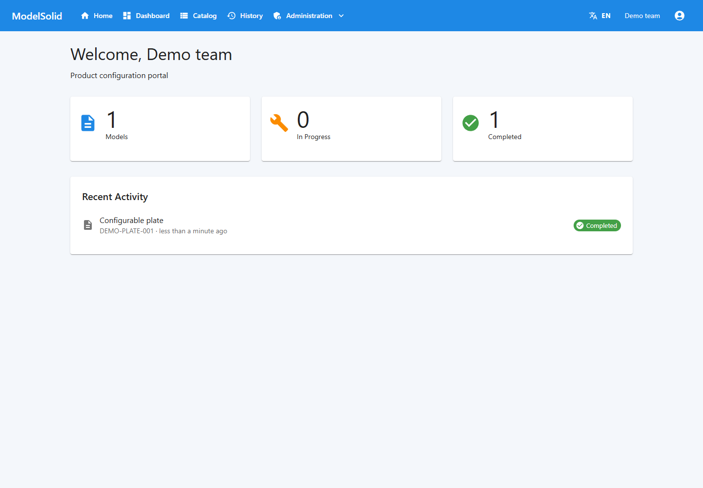
Portal dashboard: request overview. Desktop Admin and Capture are separate applications. Portal screenshot with demonstration data. Click to enlarge.
2.1 Web portal
This is the browser application. It includes Home, Dashboard, Catalog and History according to permissions. An Admin also has administration pages.
Customers need access to the portal. They do not need SOLIDWORKS installed to fill in forms.
Entry points to portal sections. Demonstration data. Click to enlarge.
2.2 ModelSolid desktop Admin
This Windows administration application opens from the Start menu or the tray agent when installed. It uses the same API and database as the portal.
Select a workspace and project before editing. Model Dimensions, Variables and Model Rules serve different purposes.
The desktop application remains the administrative reference. The web interface shares data and operations, but the screens are not identical. This manual identifies the specific route for each task.
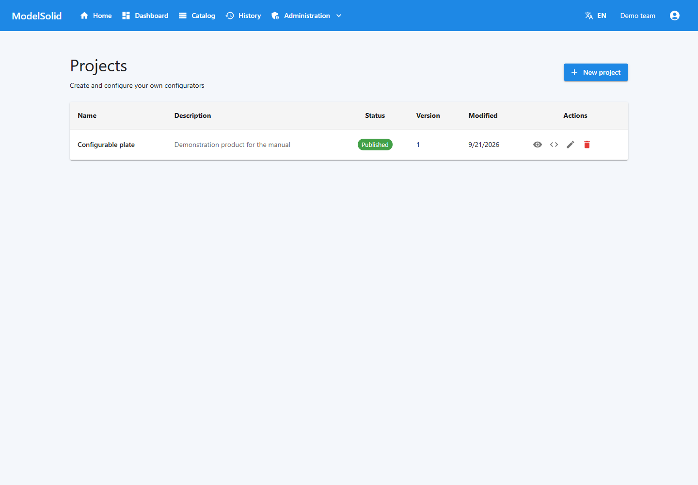
Web project list and publication status. Related portal view; it does not show this step being performed in the desktop application, CAD or terminal. Demonstration data. Click to enlarge.
2.3 Capture and worker
Capture runs inside SOLIDWORKS and records model elements. SwWorker processes requests and uses SOLIDWORKS on the generation workstation.
You can close the browser after a submission has been confirmed. Processing continues in the worker; its computer and required Windows session must remain operational.
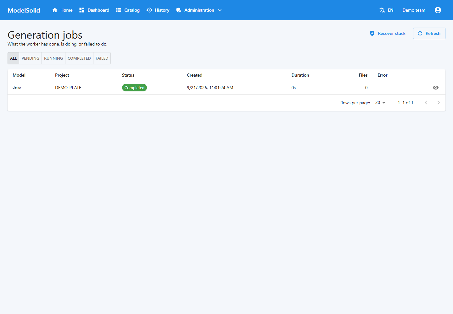
Web monitor of jobs and their statuses. Related portal view; it does not show this step being performed in the desktop application, CAD or terminal. Demonstration data. Click to enlarge.
3. Installation and first login
3.1 Installer components
The unified installer offers a full installation, API + portal only, and a custom selection.
| Component | Purpose |
|---|---|
| API + Web Portal | Store data and serve clients |
| SolidWorks Add-In | Capture models |
| SolidWorks Worker | Generate variants |
| Tray agent | Local access and control |
| Desktop Admin | Manage projects and rules |
A workstation that prepares and generates models will usually use the full installation. Sales users who only use configurators visit the portal address.
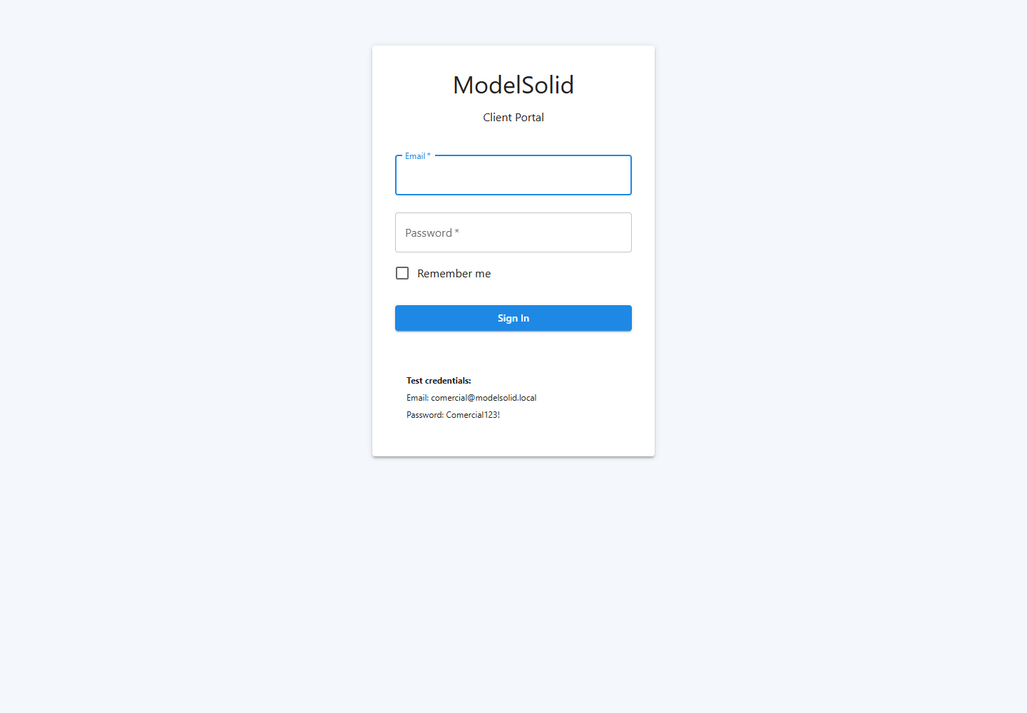
Portal sign-in screen. Related portal view; it does not show this step being performed in the desktop application, CAD or terminal. Demonstration data. Click to enlarge.
3.2 Preparing the generation workstation
- Check that SOLIDWORKS starts under the Windows account that will run the worker.
- Open a model and resolve any pending startup or licensing dialogs.
- Verify that this account can read masters and write outputs.
- Install the components from the supplied version.
- Check that the API and worker task are available.
- Run a small test generation.
The API is installed as a Windows service. The current installer configures the worker as a scheduled task in a user session to automate SOLIDWORKS. Historical documents describing it as a service do not describe this current setup.
Web monitor of jobs and their statuses. Related portal view; it does not show this step being performed in the desktop application, CAD or terminal. Demonstration data. Click to enlarge.
3.3 Portal and API addresses
In development, the portal opens at http://localhost:3000 and the API at http://localhost:5140.
For a company installation, use the addresses provided by the administrator. localhost means “this computer”: on a salesperson's laptop it does not point to the company server.
The installed portal may be served by the API. Port 3000 is used for frontend development.
Entry points to portal sections. Related portal view; it does not show this step being performed in the desktop application, CAD or terminal. Demonstration data. Click to enlarge.
3.4 Signing in
- Open the portal and enter your email and password.
- Check which sections are visible.
- If only Home appears, ask the administrator to review your user groups.
- Sign out when finished on a shared computer.
The portal, desktop application, add-in and CLI maintain sessions in different clients. Signing into one does not guarantee you are signed into the others.
Portal sign-in screen. Demonstration data. Click to enlarge.
3.5 When the installation is ready
Verify login, project access, captures and a completed generation. Seeing Home only confirms that the portal opens.
If a licence or trial message appears, save it and send it to the administrator. Changing dimensions or resubmitting requests will not resolve it.
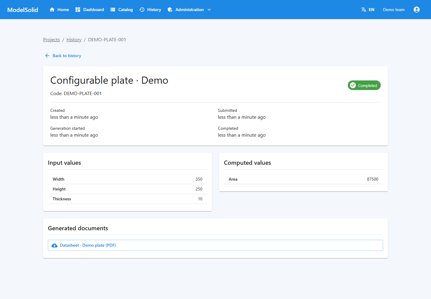
Details and results of a demonstration request. Demonstration data. Click to enlarge.
Portal sign-in screen after installing and starting the API. Portal screenshot with demonstration data. Click to enlarge.
4. Quick guide for customers and sales teams
4.1 Requesting a variant
- Sign in.
- Open Catalog.
- Select the product.
- Read field labels and units.
- Enter dimensions and options.
- Review Files to generate and additional formats.
- Click the form's submission button, usually Generate.
- Wait for confirmation and keep the instance code.
- Open History to track its status.
- Review the results once processing finishes.
The author designs each form. Buttons and layouts can differ between products.
Catalog of published products. Demonstration data. Click to enlarge.
4.2 Entering data
In a “Width (mm)” field, enter 300, not 300 mm. Respect the limits and available options.
Required fields need valid values. Calculated results come from rules. If a result does not make sense, check the inputs before using the file.
The author decides whether to show results before submission. Not every configurator includes a preview or live visual recalculation.
Example form with request inputs and options. Demonstration data. Click to enlarge.
4.3 Understanding confirmation
Confirmation means that the request has been created, not that SOLIDWORKS has finished.
If you miss the confirmation, check History before resubmitting to avoid duplicate instances.
History for locating the request by code and status. Demonstration data. Click to enlarge.
4.4 Retrieving results
The instance detail shows inputs, calculated values, dates, status and errors.
The current screen lets you download the PDF/DOCX documents listed there. CAD files and exports are saved in the output folder; this screen is not a general browser for every CAD file. The administrator should explain how to access those outputs.
Details and results of a demonstration request. Demonstration data. Click to enlarge.
4.5 If an error occurs
Keep the code, message and submitted values. Retry generation is available for failed instances. Use it after correcting the cause; it does not change the original inputs.
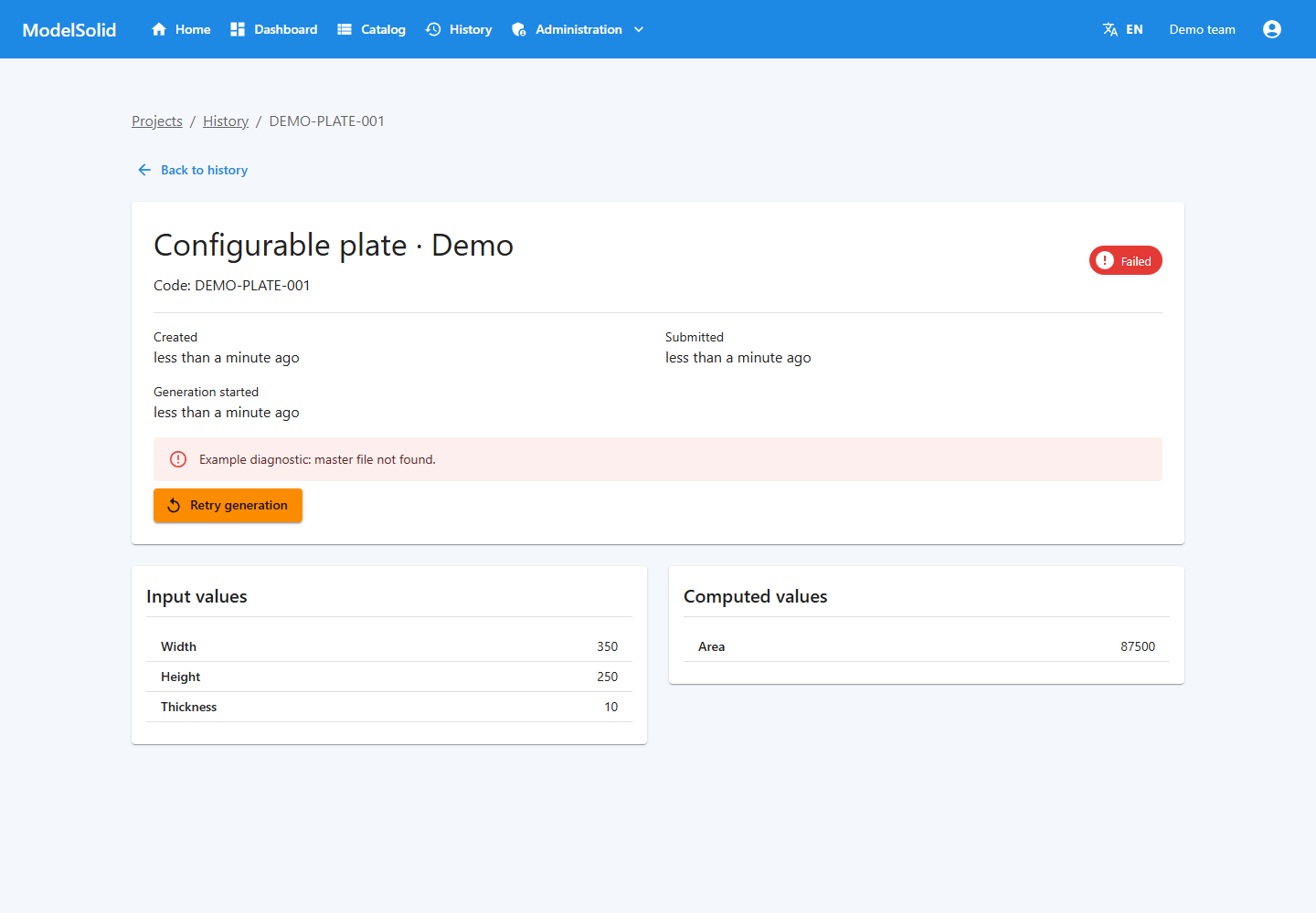
Code, diagnostic and retry action for a failed request. Demonstration data. Click to enlarge.
Example plate form: enter width, height and thickness before generating. Portal screenshot with demonstration data. Click to enlarge.
5. Essential concepts
| Concept | Meaning | Example |
|---|---|---|
| Workspace | Organisational container | Industrial products |
| User group | People allowed to access specified pages | Sales team |
| Project | Configurable product definition | Rectangular plate |
| Master | Starting engineering file | Plate.SLDPRT |
| Capture | Record of a model element | D1@Profile |
| Input | User-provided value | Width = 300 |
| Derived variable | Calculated result | Area = Width * Height |
| Dimension rule | Connection between input and dimension | D1@Profile receives Width |
| Bundle | Compiled form | HTML, CSS and JavaScript |
| Instance | Specific request | A 300 × 200 × 8 plate |
| Job | Work item processing a request | Pending generation |
| Template | Document definition | Datasheet |
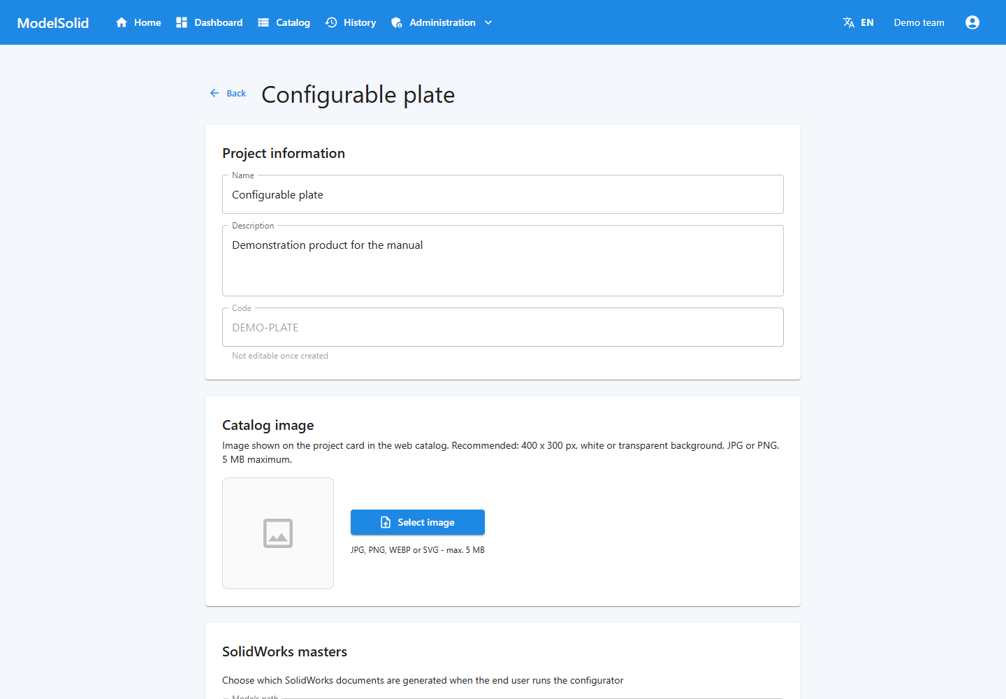
Project details: product name, code and configuration. Portal screenshot with demonstration data. Click to enlarge.
5.1 Saving, testing, publishing and generating
Save stores an edit. Test evaluates calculations. Upload the bundle installs the form. Publish puts the project in the catalog. Generate produces a specific instance.
Publishing does not design the form or automatically validate the geometry.
Web project list and publication status. Demonstration data. Click to enlarge.
5.2 Name, code and identifier
The name is human-readable. The code identifies the project in different workflows and folders. The technical identifier is usually a GUID.
The CLI needs the GUID in --project, not the card's name. You can find it in the edit address /admin/projects/<identifier>.
Project identification and settings. Demonstration data. Click to enlarge.
6. Workspaces and projects
6.1 Creating the structure
- Sign in as Admin.
- Open Workspaces in administration.
- Create the container for your product family.
- Create the project and assign it to the workspace when prompted.
- Use a stable code and a recognisable name.
- Select the project before editing or capturing.
The add-in also has + New (“+ Nuevo”). Always check the active project.
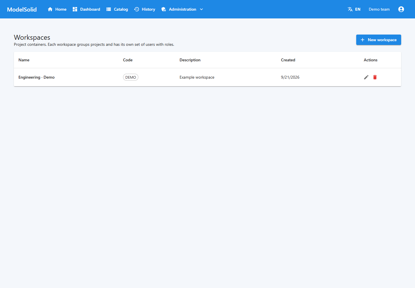
List of workspaces organizing the projects. Demonstration data. Click to enlarge.
6.2 Reviewing project details
In Administration → Projects → project, review the name, description, image, models path, document types, formats and links to rules, properties, features and templates.
The code cannot be edited through this screen after creation.
For the image, the interface accepts JPG, PNG, WEBP or SVG up to 5 MB and suggests 400 × 300 pixels. The card identifies the product; it does not guarantee a preview of the exact variant.
Project identification and settings. Demonstration data. Click to enlarge.
6.3 Paths
The models path indicates where the masters are stored. Output configuration determines where instances are written. The worker must be able to access both.
Avoid paths that exist only on the author's personal desktop. Check access from the worker's account and machine.
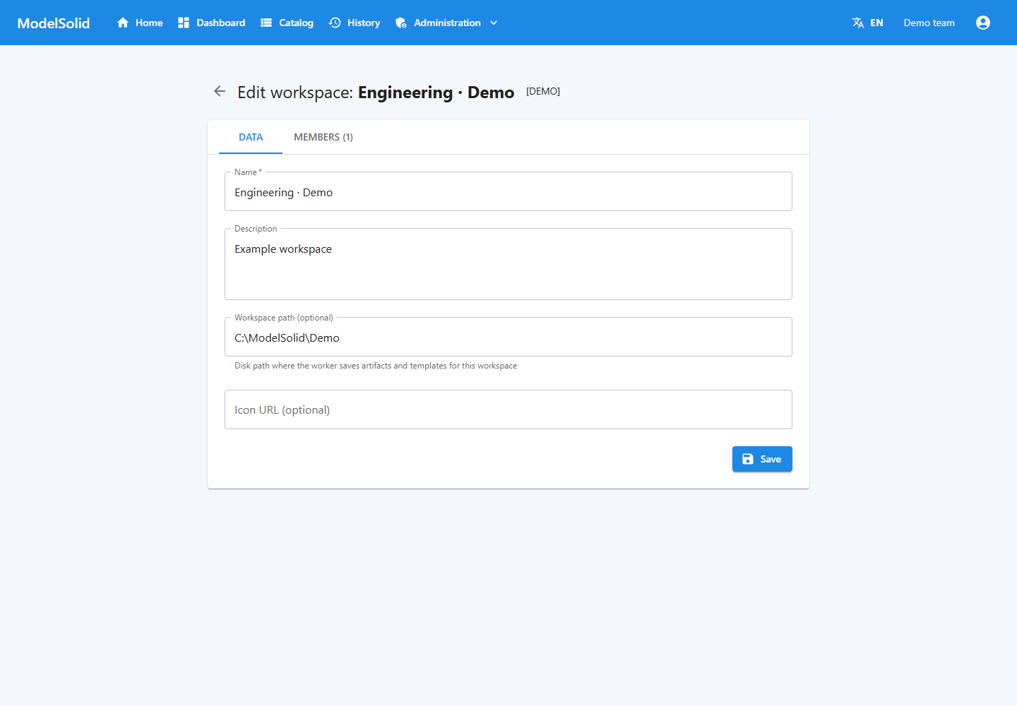
Workspace details and configured path. Demonstration data. Click to enlarge.
6.4 Concurrent editing
Desktop and web clients write to the same data. There is no general version lock covering all administrative writes: the last write can overwrite previous changes.
Coordinate one person responsible for each edit, save, and refresh when returning to work modified by someone else.
Project identification and settings. Demonstration data. Click to enlarge.
Workspaces: organizing projects and accessing their management. Portal screenshot with demonstration data. Click to enlarge.
7. Preparing engineering models
7.1 Choosing the master
It should rebuild without errors, have accessible references and support the intended parameters. Manually test small, typical and large sizes within its design range.
Automation does not itself repair a model that already fails when its dimensions change.
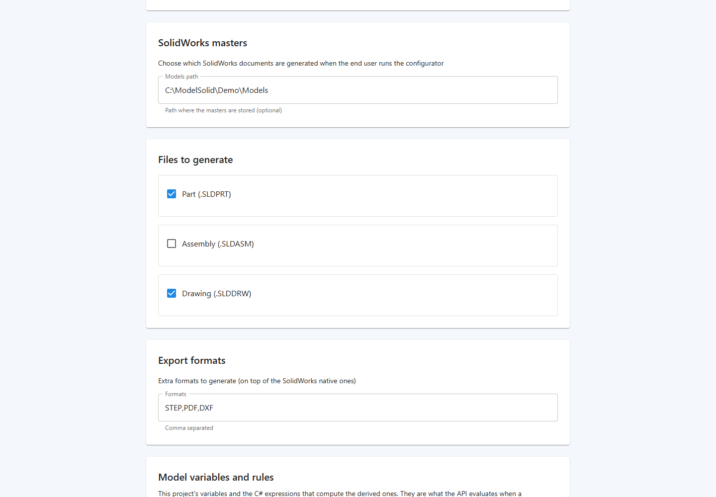
Master path and project output options in the web application. Related portal view; it does not show this step being performed in the desktop application, CAD or terminal. Demonstration data. Click to enlarge.
7.2 Step-by-step preparation
- Save the document in a controlled location.
- Rebuild and resolve errors.
- Identify the dimensions that will control the product.
- Review relations that might prevent changes.
- Identify optional features and their dependencies.
- Check properties and configurations.
- For assemblies, check components and references.
- Open the drawings you will use and review their views.
- Define acceptable ranges with engineering.
Master path and project output options in the web application. Related portal view; it does not show this step being performed in the desktop application, CAD or terminal. Demonstration data. Click to enlarge.
7.3 Names and units
A dimension such as D1@Profile includes its sketch to distinguish it from other D1 dimensions. Renaming sketches or features can change captured references.
Captured lengths use millimetres and angles use degrees. The code converts to SOLIDWORKS internal units where appropriate. Do not add manual factors of one thousand to rules to compensate.
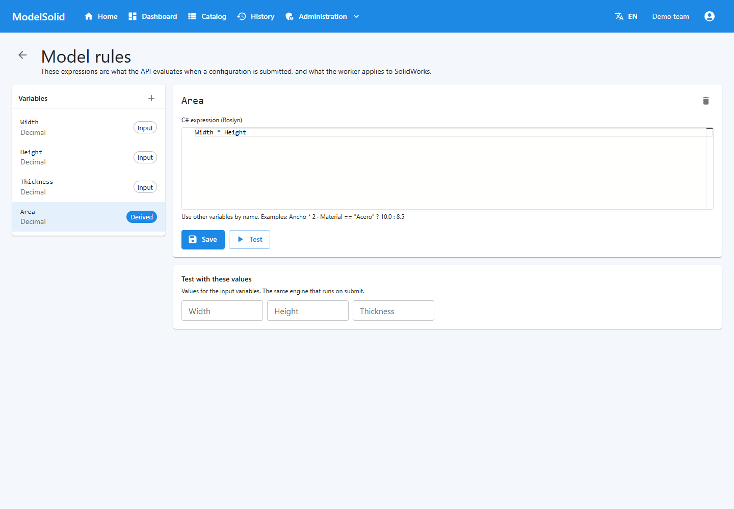
Input variables and expression for the derived Area variable. Related portal view; it does not show this step being performed in the desktop application, CAD or terminal. Demonstration data. Click to enlarge.
7.4 Different documents
Preparing a part does not automatically prepare an assembly and drawing. Configure their masters if you intend to offer those outputs.
Check assembly components and the drawing's references, views, dimensions and title blocks after generating a variant different from the master.
Master path and project output options in the web application. Related portal view; it does not show this step being performed in the desktop application, CAD or terminal. Demonstration data. Click to enlarge.
Web settings for master paths and outputs. Geometry is prepared in SOLIDWORKS, outside this screen. Portal screenshot with demonstration data. Click to enlarge.
8. Capturing models in SOLIDWORKS®
8.1 Enabling Capture
With the component installed, open Tools → Add-ins and enable ModelSolid Capture. The panel appears in the side task pane.
For development, dev-scripts/register-swaddin.ps1 requires administrative permissions and may close and reopen SOLIDWORKS. Save your documents first. For a user installation, use the corresponding installer.
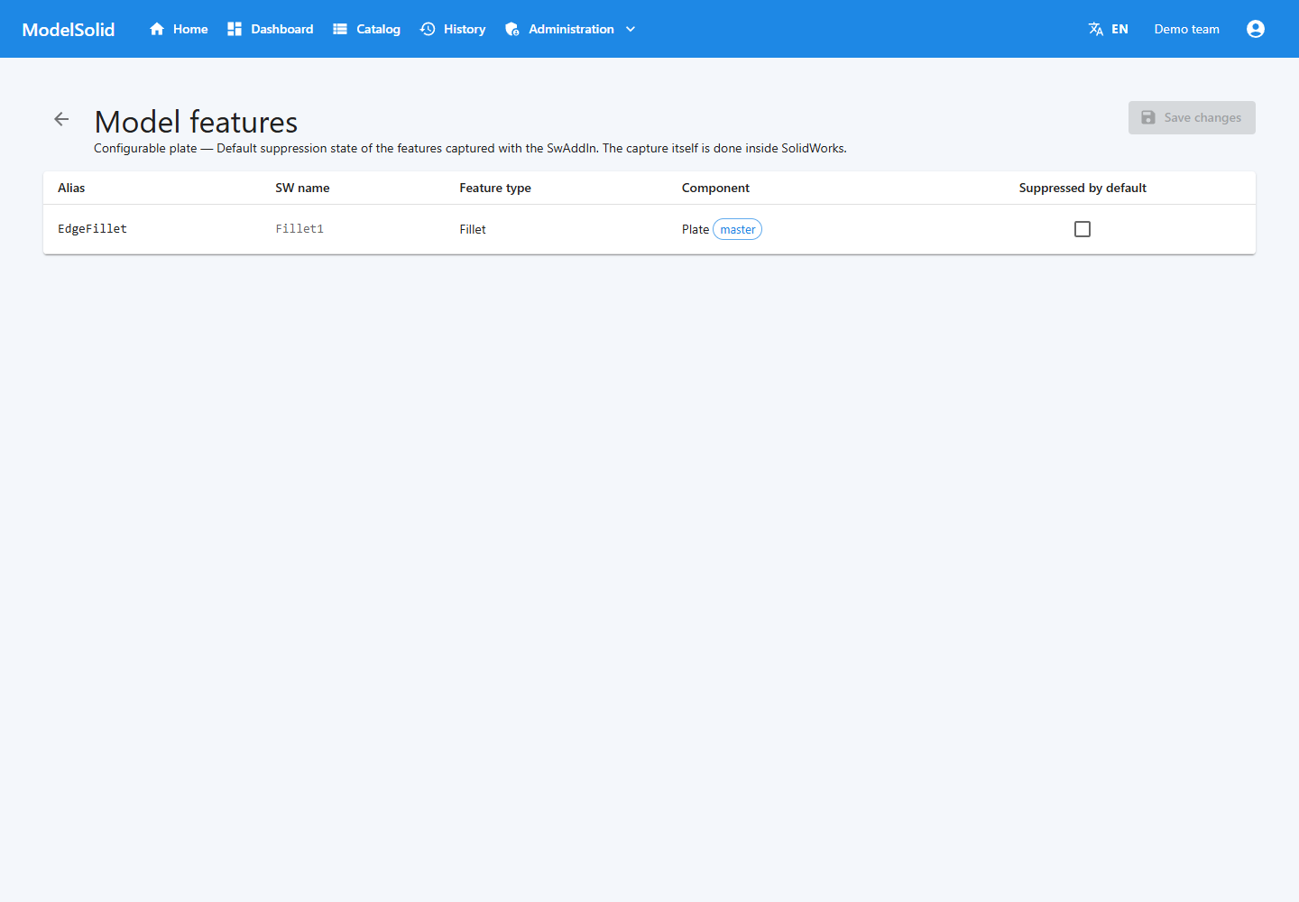
Features registered by Capture, viewed from the web application. Related portal view; it does not show this step being performed in the desktop application, CAD or terminal. Demonstration data. Click to enlarge.
8.2 Connecting
- Click Login.
- Enter the API URL.
- Enter your email and password.
- Enable Remember password on this computer if appropriate.
- Select the project.
- Check the active document.
The add-in uses Windows protection for sensitive session data it persists. Do not share its session files as an access method.
Portal sign-in screen. Related portal view; it does not show this step being performed in the desktop application, CAD or terminal. Demonstration data. Click to enlarge.
8.3 Adding a master
- Open and save the document.
- Verify the selected project.
- Click Add active document as Master (“Añadir doc activo como Master”).
- Check the resulting name and path.
- Select its record in Captured Models.
Registering a part may save a copy with a name associated with the project code in its models path and reopen it. For other types, the current path is registered. Check which file remains open.
Capturing does not automatically transfer all dependencies to any remote server. Verify paths from the worker.
Master path and project output options in the web application. Related portal view; it does not show this step being performed in the desktop application, CAD or terminal. Demonstration data. Click to enlarge.
8.4 Capturing a dimension
- Select the dimension.
- Click Capture selected dimension (“Capturar dimensión seleccionada”).
- Check the full name, value and unit.
- Repeat for the dimensions you need.
If it already exists, a duplicate warning does not mean its value has been updated.
Input variables and expression for the derived Area variable. Related portal view; it does not show this step being performed in the desktop application, CAD or terminal. Demonstration data. Click to enlarge.
8.5 Capturing all dimensions
Capture all dimensions (“Capturar todas las dimensiones”) adds newly found dimensions and skips existing records.
It does not automatically remove old captures or synchronise all their values. Dimensions may be hidden or belong to another configuration.
After renaming or removing elements, compare captures, deliberately remove obsolete ones and review their rules.
Input variables and expression for the derived Area variable. Related portal view; it does not show this step being performed in the desktop application, CAD or terminal. Demonstration data. Click to enlarge.
8.6 Applying values to the open document
The panel's Model Rules section shows alias, SOLIDWORKS name, value and unit.
- Edit a value.
- Confirm it by leaving the cell.
- Click Apply to model (“Aplicar al modelo”).
- Review the message about applied or unresolved dimensions.
- Inspect the geometry before saving.
This modifies the open document. It does not replace saving C# expressions in Admin or create a portal request.
Example form with request inputs and options. Related portal view; it does not show this step being performed in the desktop application, CAD or terminal. Demonstration data. Click to enlarge.
8.7 Features
Select the feature in the tree and click Capture selected feature (“Capturar feature seleccionado”). Check its name and suppression state.
Suppressing disables the feature. Dependent features may also be affected.
Features registered by Capture, viewed from the web application. Related portal view; it does not show this step being performed in the desktop application, CAD or terminal. Demonstration data. Click to enlarge.
8.8 Properties
Import all custom props (“Importar todas las custom props”) records document properties, including configuration properties that are found.
Check name, scope and value. A text property named Material does not guarantee that the physical material or density changes.
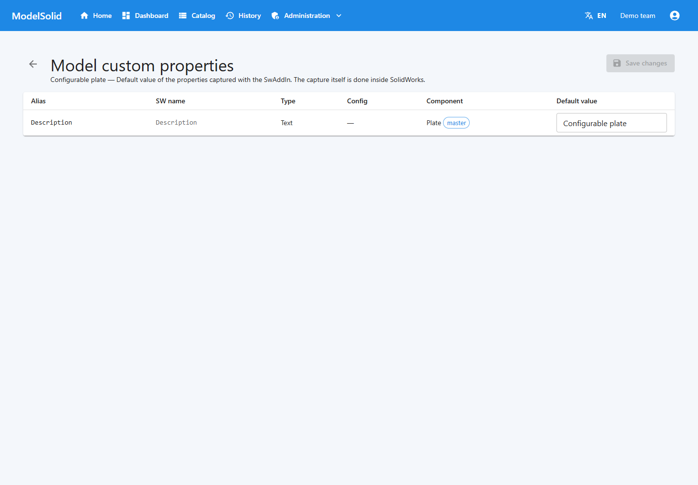
Captured properties and their default values. Related portal view; it does not show this step being performed in the desktop application, CAD or terminal. Demonstration data. Click to enlarge.
8.9 Drawings
Activate the .SLDDRW and click Add active drawing (“Añadir drawing activo”). Check its association and that references are accessible to the worker.
Then request the drawing and relevant formats in the output configuration.
Master path and project output options in the web application. Related portal view; it does not show this step being performed in the desktop application, CAD or terminal. Demonstration data. Click to enlarge.
8.10 Formats and options
Add common formats (“Añadir formatos comunes”) creates common format records. Select a format, edit its JSON options and click Save options (“Guardar opciones”).
STEP example:
{"ap": 242}
STL example:
{"binary": false}
Use each object for the corresponding format. The enabled indicators in the list are not editable switches in this revision.
Request formats through the project or portal. Recording their options does not request every file for each instance.
Master path and project output options in the web application. Related portal view; it does not show this step being performed in the desktop application, CAD or terminal. Demonstration data. Click to enlarge.
8.11 Removing captures
The Delete key removes selected records in several lists: dimensions, features, properties and captured models. The panel table also allows deleting a dimension capture.
Deleting a captured model deletes its dependent captures. Review the selection and rules first. Removing a capture record is not the same as deleting a feature from the SOLIDWORKS file.
Features registered by Capture, viewed from the web application. Related portal view; it does not show this step being performed in the desktop application, CAD or terminal. Demonstration data. Click to enlarge.
Web view of features already captured. Capture itself uses the add-in inside SOLIDWORKS. Portal screenshot with demonstration data. Click to enlarge.
9. Defining variables
9.1 Inputs and derived variables
A variable without an expression receives an input. A variable with an expression is calculated from other values.
| Name | Type | Initial value | Expression | Purpose |
|---|---|---|---|---|
| Width | Decimal | 300 | Empty | Width |
| Height | Decimal | 200 | Empty | Height |
| Thickness | Decimal | 8 | Empty | Thickness |
| Area | Decimal | As configured | Width * Height |
Area in mm² |
| Material | String | Steel | Empty | Commercial option |
| IncludeHoles | Bool | true | Empty | Hole option |
Example identifiers are in English. The visible label may be “Width (mm)” or its translation while the variable remains named Width.
Input variables and expression for the derived Area variable. Demonstration data. Click to enlarge.
9.2 Creating a variable in desktop Admin
- Open the project in Admin.
- Go to Variables.
- Click Add variable.
- Enter name, label, type and default value.
- Mark it as required if appropriate.
- For a derived variable, enter the expression.
- Confirm and click Save changes.
- Refresh to verify the persisted data.
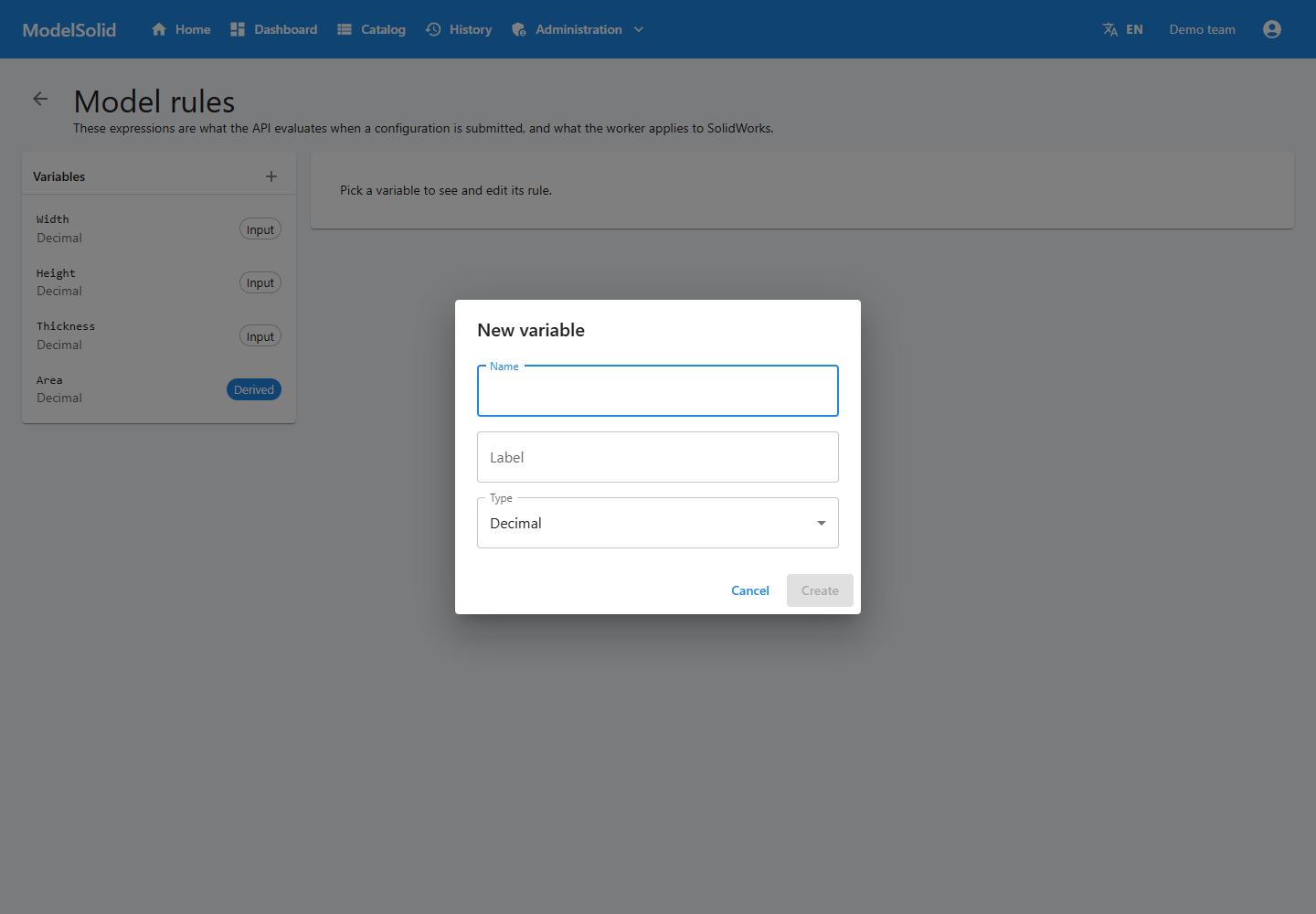
Variable creation dialog in the portal. Related portal view; it does not show this step being performed in the desktop application, CAD or terminal. Demonstration data. Click to enlarge.
9.3 Types
| Type | Content | Typical use |
|---|---|---|
| String | Text | Reference, material or description |
| Int | Integer | Whole quantities |
| Decimal | Number with decimal places | Dimensions |
| Bool | True or false | Binary options |
| DateTime | Date and time | Time-related data |
| List | Collection | A structure the form must handle |
The type does not automatically create the visual control. A text variable can appear as a dropdown if the author programs it that way.
Variable creation dialog in the portal. Demonstration data. Click to enlarge.
9.4 Names
Use identifiers such as Width, UnitPrice or IncludeHoles. Avoid spaces, punctuation and reserved names. Do not treat Width and width as interchangeable in C# expressions.
Renaming a variable requires reviewing expressions, the form and capture associations. Changing only its visible label is a separate operation.
Input variables and expression for the derived Area variable. Demonstration data. Click to enlarge.
9.5 Initial values and limits
The default value lets you start and test. It is not an acceptable-range limit.
Define ranges with engineering, reflect them in the form and check server validation for the specific case. Marking a field as required does not prove that every accepted number produces valid geometry.
Example form with request inputs and options. Demonstration data. Click to enlarge.
Web dialog for creating a variable and selecting its type. Portal screenshot with demonstration data. Click to enlarge.
10. Creating and testing rules
10.1 Two levels
A variable expression calculates area, price or a selection. A dimension rule takes the result to a model dimension.
The user enters Width = 300
Area calculates Width * Height
The D1@Profile rule returns Width
SOLIDWORKS receives 300 mm for that dimension
Creating Width without binding it does not guarantee that the model's width changes.
Input variables and expression for the derived Area variable. Demonstration data. Click to enlarge.
10.2 Basic expressions
These are C# expressions. Do not prefix them with an equals sign.
| Goal | Expression |
|---|---|
| Use an input | Width |
| Add clearance | Width + 5.0 |
| Calculate half | Width / 2.0 |
| Multiply | Width * Height |
| Condition | Width > 300 ? 10.0 : 8.0 |
| Round | Math.Round(Width / 3.0, 2) |
| Choose text | Material == "Steel" ? "ST" : "OTHER" |
| Invert an option | !IncludeHoles |
Use a decimal point. To divide integers while retaining a fractional result, use a divisor such as 2.0.
Helpers include ROUND and CLAMP. Clamping modifies the result; it is not the same as rejecting an input with an error message.
Input variables and expression for the derived Area variable. Demonstration data. Click to enlarge.
10.3 Editing expressions on the web
- Open Administration → Projects → project → Edit rules.
- Select the variable.
- Enter the expression.
- Review the test values.
- Click Test.
- Save.
- Reopen or reload to verify what was saved.
This screen works with variables and expressions. Do not confuse it with the desktop dimension-rule table.
Input variables and expression for the derived Area variable. Demonstration data. Click to enlarge.
10.4 Dimension defaults
In Model Dimensions, review alias, component, SOLIDWORKS name, value and unit. To change a value, confirm the cell and click Save values.
Changing stored data does not modify already-generated files and is not equivalent to opening and saving the master.
Input variables and expression for the derived Area variable. Related portal view; it does not show this step being performed in the desktop application, CAD or terminal. Demonstration data. Click to enlarge.
10.5 Binding dimensions in desktop Admin
- Open Model Rules.
- Locate the model and dimension.
- Select a variable or enter an expression.
- Confirm the cell.
- Click Save and check for saving errors.
- Click Test all.
- Correct, save and repeat if errors occur.
Save before Test all: this desktop action reads rules persisted in the API. An unsaved expression may not be the one being tested.
The test uses available defaults. It does not open SOLIDWORKS or prove the model rebuilds. For expressions depending on derived values, also check the complete generation workflow.
Input variables and expression for the derived Area variable. Related portal view; it does not show this step being performed in the desktop application, CAD or terminal. Demonstration data. Click to enlarge.
10.6 Dependencies and diagnosis
If Area depends on Width and Height, both must be available. Avoid cycles: A depends on B and B depends on A.
On error, check the exact name, existence, type, value used and saved expression. Avoid denominators that can become zero.
Editing and executing arbitrary rules is restricted to Admin. Use trusted authors: Roslyn filtering must not be treated as full isolation for third-party code.
Code, diagnostic and retry action for a failed request. Demonstration data. Click to enlarge.
Rule editor: Area is calculated using Width * Height. Portal screenshot with demonstration data. Click to enlarge.
11. Features, properties and replacements
11.1 Optional features
Captured features have an alias and an initial suppression state. The worker looks for an associated value; if none is found, it uses the captured state.
True means suppressed and false means active.
For an “Include holes” question, a clear arrangement would be:
Input: IncludeHoles
Feature alias and derived variable: SuppressHoles
SuppressHoles expression: !IncludeHoles
Including holes produces SuppressHoles = false. Check that the actual alias matches the intended variable and generate both options.
On the web project page, Features lets you review and adjust defaults. Capturing is done in SOLIDWORKS.
Features registered by Capture, viewed from the web application. Demonstration data. Click to enlarge.
11.2 Custom properties
The worker matches properties to variables by alias or name and uses the initial value when none is associated. Configuration scope is part of the capture.
For example, CustomerReference can supply a property with that alias. Review its value and configuration inside the generated file.
On the web, open Custom properties from the project page. A text property does not automatically cause a physical model change.
Captured properties and their default values. Demonstration data. Click to enlarge.
11.3 Replacements
The worker supports sets of candidate models identified by a token. A variable with that name selects an allowed candidate. Without a valid selection, it may retain the original component and log a warning.
The current Capture panel does not provide a complete visible workflow for creating and editing these sets. Preparing them requires technical work using the API functionality. Do not assume that a wizard described in planning documents is already available in the panel.
If a project uses prepared replacements, test each candidate and inspect the actual assembly. A Completed status does not replace that inspection.
Master path and project output options in the web application. Related portal view; it does not show this step being performed in the desktop application, CAD or terminal. Demonstration data. Click to enlarge.
Captured custom properties: reviewing and editing default values. Portal screenshot with demonstration data. Click to enlarge.
12. Building the web form
This chapter is for authors. Users who only submit requests can continue to chapter 14.
An example form loaded inside the portal. Its code is prepared and built using the authoring tools. Portal screenshot with demonstration data. Click to enlarge.
12.1 What you build
The configurator is an HTML, CSS and TypeScript application compiled into a bundle. The portal opens it inside an isolated frame.
The current workflow does not have a drag-and-drop form designer. Defining variables does not automatically design their screen.
Example form with request inputs and options. Demonstration data. Click to enlarge.
12.2 Preparing local tools
From the repository root:
pnpm install
pnpm --filter @modelsolid/vite-plugin build
pnpm --filter create-modelsolid-form build
pnpm --filter @modelsolid/cli build
You need Node compatible with the dependencies, pnpm and an editor. This workflow uses the local tools from this revision; if you have a CLI distribution for your installation, follow its version-specific instructions.
Example form with request inputs and options. Related portal view; it does not show this step being performed in the desktop application, CAD or terminal. Demonstration data. Click to enlarge.
12.3 Creating the form
Example with the repository in C:\Programacion\ModelSolid and the form outside it:
$cliPath = 'C:\Programacion\ModelSolid\packages\cli\dist\index.js'
Set-Location C:\Programacion
node $cliPath init plate-configurator
Set-Location .\plate-configurator
pnpm add -D "file:C:/Programacion/ModelSolid/packages/vite-plugin"
The final command links the local plugin and installs dependencies. Adjust paths to your computer. Do not reuse an existing folder: init expects to create a new one.
The template contains modelsolid.json, src/main.ts and Vite configuration. Its initial fields are examples you must adapt.
Example form with request inputs and options. Related portal view; it does not show this step being performed in the desktop application, CAD or terminal. Demonstration data. Click to enlarge.
12.4 Connecting to the project
Edit modelsolid.json:
{
  "apiUrl": "http://localhost:5140",
  "projectId": "REPLACE-WITH-THE-ACTUAL-GUID"
}
Replace the placeholder with the actual identifier and use your installation's API. In the same terminal:
node $cliPath login
node $cliPath whoami
node $cliPath pull-types
pull-types generates .modelsolid/types.d.ts. Run it again when variables change. Fetching types helps the editor; it does not draw controls.
The CLI saves the session outside the project, in the user's .modelsolid folder. Interactive password input is not hidden in this revision; avoid entering it while sharing or recording the terminal.
Project identification and settings. Related portal view; it does not show this step being performed in the desktop application, CAD or terminal. Demonstration data. Click to enlarge.
12.5 Designing fields
Define label, exact identifier, unit, control, initial value, limits and help text.
The initial template uses lowercase example names. Change them if the project defines Width or Height.
The current typed bridge declares submit with a dictionary of numbers. This chapter's example is limited to numeric inputs. If you need to send text, lists or booleans, first review and adapt the configurator and portal contract with your technical administrator; the existence of those variable types in Admin does not automatically extend the template's contract.
Example form with request inputs and options. Demonstration data. Click to enlarge.
12.6 Minimal example
This code is a starting point for src/main.ts with Width, Height and Thickness inputs. They must exist in the project and have their dimension rules configured separately.
import { submit } from 'virtual:modelsolid'

const app = document.querySelector<HTMLDivElement>('#app')!
app.innerHTML = `
  <h1>Configurable plate</h1>
  <form id="configuration">
    <label>Width (mm)
      <input name="Width" type="number" value="300"
        min="100" max="600" step="0.1" required>
    </label>
    <label>Height (mm)
      <input name="Height" type="number" value="200"
        min="100" max="400" step="0.1" required>
    </label>
    <label>Thickness (mm)
      <input name="Thickness" type="number" value="8"
        min="3" max="20" step="0.1" required>
    </label>
    <button type="submit">Generate</button>
    <p id="status" role="status"></p>
  </form>
`

const form = document.querySelector<HTMLFormElement>('#configuration')!
const status = document.querySelector<HTMLParagraphElement>('#status')!

form.addEventListener('submit', (event) => {
  event.preventDefault()
  if (!form.reportValidity()) return

  const fields = new FormData(form)
  const values = {
    Width: Number(fields.get('Width')),
    Height: Number(fields.get('Height')),
    Thickness: Number(fields.get('Thickness')),
  }

  if (!Object.values(values).every(Number.isFinite)) {
    status.textContent = 'Check the numeric values.'
    return
  }

  const sent = submit(values)
  status.textContent = sent
    ? 'Request sent to the portal. Wait for confirmation.'
    : 'Preview: no request has been submitted.'
})
submit communicates data to the portal. Its result does not certify API acceptance or completed generation. The final confirmation or error appears in the portal.
These limits are for learning. Define product limits with engineering and check server validation.
Example form with request inputs and options. Related portal view; it does not show this step being performed in the desktop application, CAD or terminal. Demonstration data. Click to enlarge.
12.7 Previewing and building
pnpm dev
Open the address shown by Vite. Outside the portal, submission is in preview mode and creates no jobs.
Check TypeScript and build:
pnpm build
Stop the development server with Ctrl+C. If you open another terminal, define $cliPath again before using it.
Example form with request inputs and options. Related portal view; it does not show this step being performed in the desktop application, CAD or terminal. Demonstration data. Click to enlarge.
12.8 Uploading the bundle
From the form folder, signed in as Admin:
node $cliPath push
The CLI builds with Vite, packages dist and uploads the bundle. Running pnpm build first also checks TypeScript through the template's script.
Uploading replaces the served form. Keep the sources and a working version. The ZIP needs index.html at its root; use the CLI to prepare it.
Uploading the bundle does not itself change the project's publication status.
Catalog of published products. Related portal view; it does not show this step being performed in the desktop application, CAD or terminal. Demonstration data. Click to enlarge.
12.9 Isolated frame
Use virtual:modelsolid for submission and the language functions provided by the template. Do not depend on the portal's session storage or HTML.
To extend integration, review the actual plugin contract. Recalculation functions described as goals in older documents should not be assumed available in every bundle.
Example form with request inputs and options. Demonstration data. Click to enlarge.
13. Publishing and updating
13.1 Pre-publication review
Check masters, captures, variables, saved rules, bundle, outputs, templates and worker access.
Publishing determines availability. Even if the system allows it, you must verify that the product is ready to receive requests.
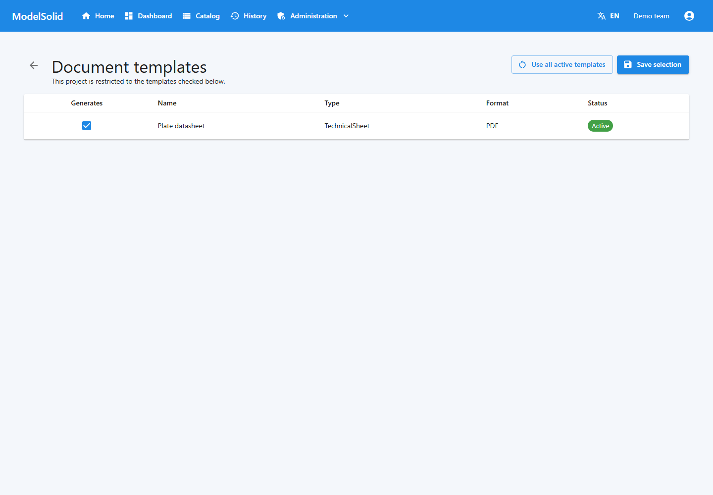
Templates selected to generate project documents. Demonstration data. Click to enlarge.
13.2 Publishing from desktop Admin
- Select the workspace.
- Open Stage 1: Workspace Setup → Published Apps.
- Click Publish App.
- Select the project.
- Confirm.
- Check the card and form in the catalog.
The web interface also offers publishing from the administrative project list. Review the displayed status after the operation.
Web project list and publication status. Related portal view; it does not show this step being performed in the desktop application, CAD or terminal. Demonstration data. Click to enlarge.
13.3 Testing as an end user
Use a User account with Catalog and History access. Admin can hide permission problems because it has full access.
Enter values different from the defaults, submit, wait and inspect files.
Catalog of published products. Demonstration data. Click to enlarge.
13.4 Unpublishing
Select the project in Published Apps, click Unpublish and confirm. It returns to draft and leaves the catalog. Existing instances are preserved.
Unpublishing does not cancel submitted jobs. For maintenance, review the queue and coordinate the worker.
Web project list and publication status. Demonstration data. Click to enlarge.
13.5 Updating
Keep a working copy. When changes affect current use, temporarily withdraw the product. Update master and captures, then variables and rules, then form and types.
Run a complete generation before reopening. Entering a version number in the project details does not guarantee that all previous masters and bundles are automatically archived.
Project identification and settings. Demonstration data. Click to enlarge.
Project administration: publication status and available actions. Portal screenshot with demonstration data. Click to enlarge.
14. Choosing output files
14.1 Types
| Output | Purpose | Requirement |
|---|---|---|
| SLDPRT | Editable part | Part master |
| SLDASM | Assembly | Master and components |
| SLDDRW | Drawing | Master and references |
| STEP | Geometry exchange | Compatible model |
| IGES | Geometry exchange | Compatible model |
| Parasolid | Solid exchange | Compatible model |
| STL | Mesh | Model and options |
| DXF | 2D exchange depending on document | Prepared source |
| CAD PDF | Representation from SOLIDWORKS | Suitable source and export |
| Document PDF/DOCX | Quote, datasheet or BOM | Template and data |
A drawing PDF and a datasheet PDF are different results.
Master path and project output options in the web application. Demonstration data. Click to enlarge.
14.2 Project defaults
Select part, assembly and drawing in the project details. Specify additional formats and save.
Registering a master does not require generating it: its output must be requested.
Master path and project output options in the web application. Demonstration data. Click to enlarge.
14.3 Per-request values
Users can change Files to generate. Their selections override the corresponding project values for that job.
Explicitly leaving additional formats empty means none; it does not automatically restore the project's formats.
Example form with request inputs and options. Demonstration data. Click to enlarge.
14.4 Format captures
They provide the source document and options. A captured but disabled format may be omitted even when requested.
If an output is missing, check files and logs. Requesting DXF does not guarantee a valid sheet-metal flat pattern unless the appropriate document and workflow have been prepared.
Master path and project output options in the web application. Related portal view; it does not show this step being performed in the desktop application, CAD or terminal. Demonstration data. Click to enlarge.
14.5 Location
Files are written to the instance output. Documents are saved alongside models when the job reports that path; there is a fallback document location when it is unavailable.
The administrator should document access for the installation. Do not assume identical folders or drive letters on every machine.
Workspace details and configured path. Related portal view; it does not show this step being performed in the desktop application, CAD or terminal. Demonstration data. Click to enlarge.
Selecting native files and project export formats. Portal screenshot with demonstration data. Click to enlarge.
15. Templates and documents
15.1 Types available through the interface
The web screen creates PDF templates with built-in layouts for Quote, Datasheet and BOM.
Additional services and types exist, including DOCX, but this screen is not a visual editor for arbitrary layouts. An internal Manual or Custom type does not imply that a layout is ready.
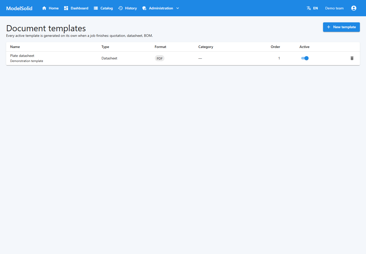
List of template types and activation status. Demonstration data. Click to enlarge.
15.2 Creating a template
- Open Administration → Document templates.
- Click New template.
- Enter a name.
- Select an offered type.
- Create the template.
- Check that it is active.
- Generate a test instance and inspect the PDF.
Deactivation prevents future generation of that template without deleting it. The interface states that deleting the definition does not delete documents already generated.
List of template types and activation status. Demonstration data. Click to enlarge.
15.3 Per-project selection
- Open the project details.
- Click Choose templates.
- Select the desired templates.
- Click Save selection.
- Check whether the project is restricted or uses all active templates.
An empty selection restores the use of all active templates. Unchecking everything does not mean generating zero documents.
Use all active templates removes the restriction. Distinguish a globally inactive template from an active template that is not selected for a project.
Templates selected to generate project documents. Demonstration data. Click to enlarge.
15.4 Reviewing documents
Check instance, dimensions, units, names and commercial data. A file that opens correctly can still be incomplete if it does not receive the expected data.
A document BOM should not be assumed equivalent to a complete extraction of every assembly component. Validate its contents for the project before using it for purchasing or manufacturing.
Details and results of a demonstration request. Demonstration data. Click to enlarge.
Selecting the document templates used by the project. Portal screenshot with demonstration data. Click to enlarge.
16. History and jobs
16.1 States
A User sees their own instances. Admin can see everyone's.
| State | Meaning | Action |
|---|---|---|
| Draft | Not submitted yet | Review the workflow that created it |
| Submitted | Sent for generation | Wait or check the queue |
| Generating | Being processed | Track status |
| Completed | Processing finished | Review outputs |
| Error | Generation failed | Investigate the cause |
The normal form creates and submits the request. The existence of Draft does not imply that every configurator has a Save draft button.
History for locating the request by code and status. Demonstration data. Click to enlarge.
16.2 Details
Review code, name, dates, inputs and results. The screen periodically refreshes submitted or generating instances.
Use the application's buttons to download documents: they include authentication. A protected URL opened without a session may fail.
Details and results of a demonstration request. Demonstration data. Click to enlarge.
16.3 Monitoring
In Administration → Jobs, review work items and statuses. The instance describes what was requested; the job describes the execution processing it.
Match instance code, job identifier and time. Pending can mean resources are busy, not that a failure has occurred.
Web monitor of jobs and their statuses. Demonstration data. Click to enlarge.
16.4 Retrying
- Open the failed instance.
- Identify the cause.
- Correct the file, permission, rule or availability problem.
- Check the worker.
- Click Retry generation once.
- Track the new attempt.
Do not force retries on jobs that are still active. Create another request to change the values.
Code, diagnostic and retry action for a failed request. Demonstration data. Click to enlarge.
Request history: reviewing the code, status and date. Portal screenshot with demonstration data. Click to enlarge.
17. Users, roles and permissions
17.1 Roles
| Capability | Admin | User |
|---|---|---|
| Project and user management | Yes | No |
| Rule editing and bundle upload | Yes | No |
| Portal pages | All | According to groups |
| History | All users | Own instances only |
The internal licensing role is not a profile that a company administrator should assign to provide sales access.
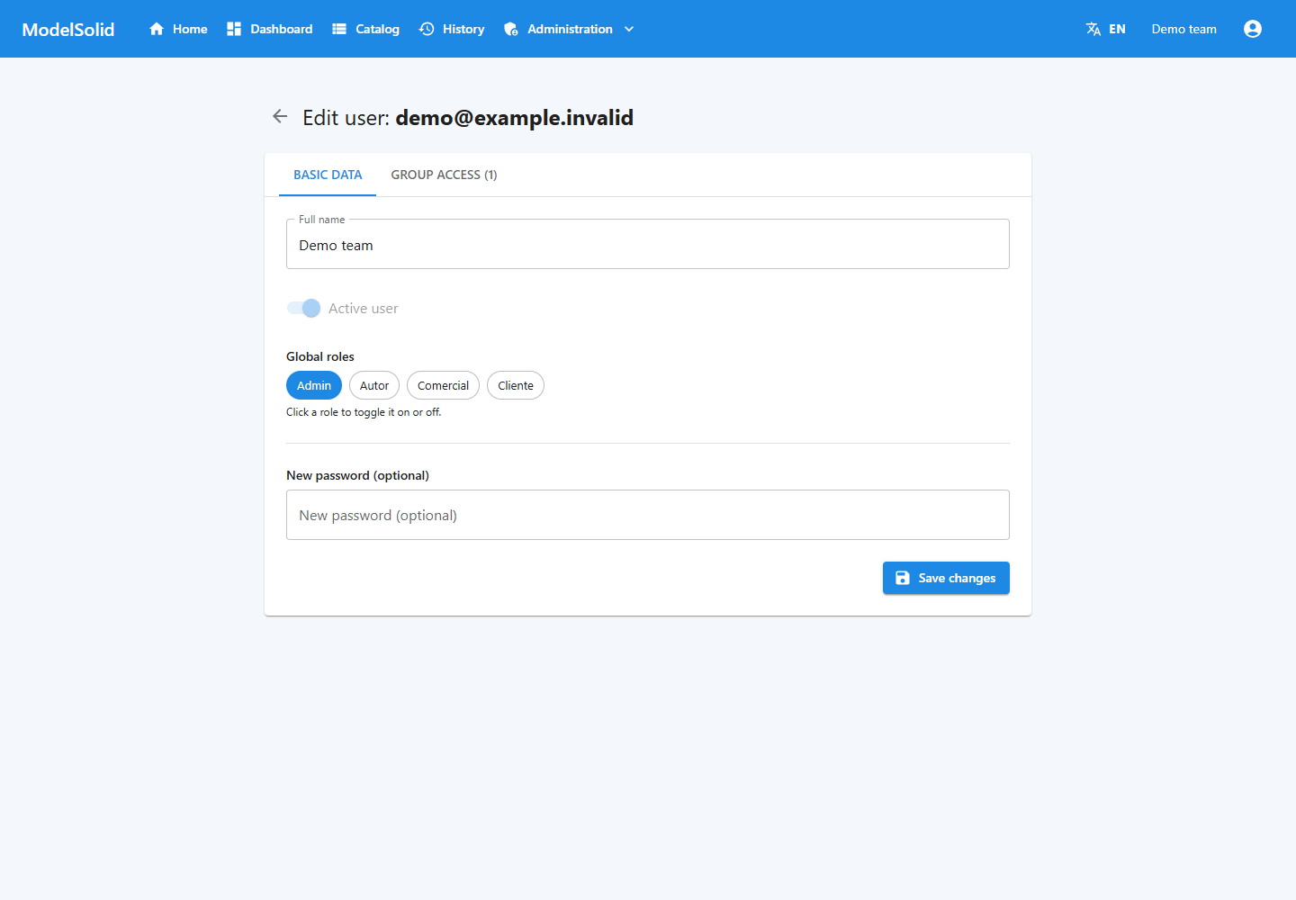
User details and role assignment. Demonstration data. Click to enlarge.
17.2 Creating a user
- Open Administration → Users.
- Click New user.
- Enter details and an initial password.
- Select Portal user or Administrator.
- Save.
- Assign the required groups.
- Check access with the new account.
An account without groups may only have Home available.
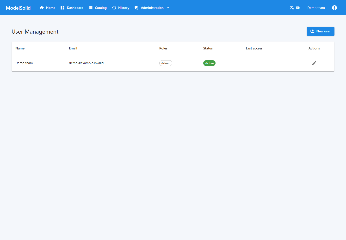
User administration and access to New user. Demonstration data. Click to enlarge.
17.3 Creating a user group
- Open User groups.
- Create a name and code.
- Under Portal pages, enable Dashboard, Catalog and History as appropriate.
- Under Members, add people.
- Save and test using one of their accounts.
You can also change memberships when editing a user.
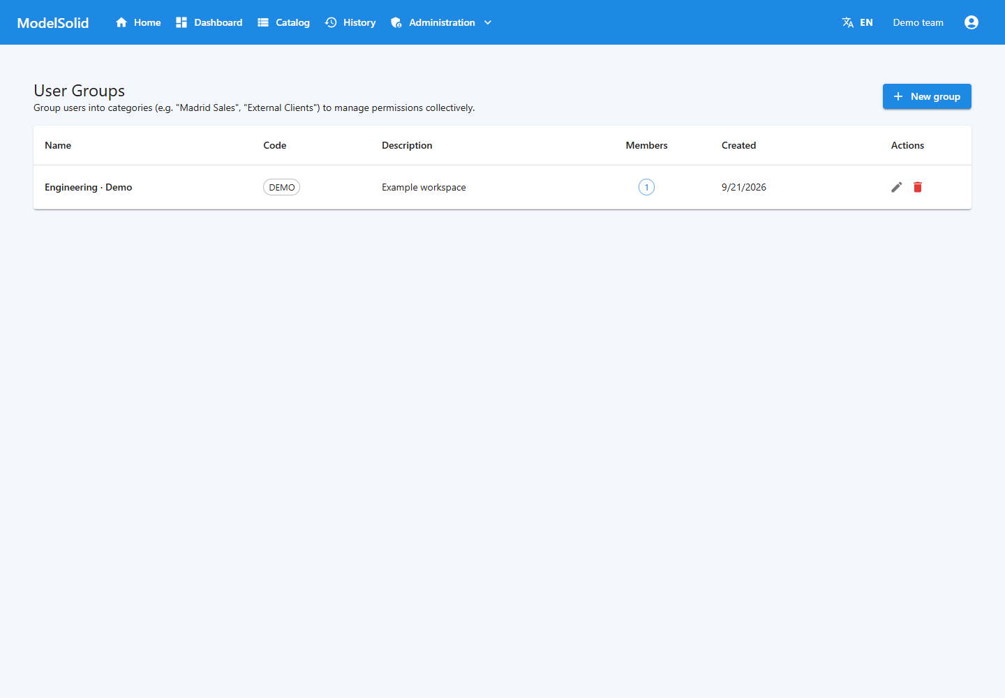
User groups and their members. Demonstration data. Click to enlarge.
17.4 Combining permissions
Allowed pages are combined. Catalog in one group and History in another grant both to someone belonging to both groups.
Removing a page from one group does not revoke it if another group still permits it. Review all memberships.
A workspace organises projects; a user group controls pages. Do not assume that this page configuration creates a private product-by-product catalog.
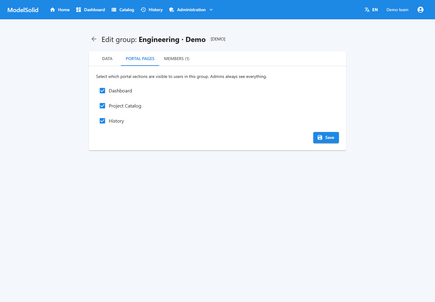
Portal pages allowed for the group. Demonstration data. Click to enlarge.
17.5 Refreshing the session
After changing groups or pages, reload or sign in again. When changing a role, sign out and sign back in to receive the updated role.
Do not test permissions only as Admin: it always sees all pages.
Portal sign-in screen. Demonstration data. Click to enlarge.
User group: members and allowed pages. Portal screenshot with demonstration data. Click to enlarge.
18. Lookup tables
These let you manage tabular data, such as materials or factors, from the web and desktop applications.
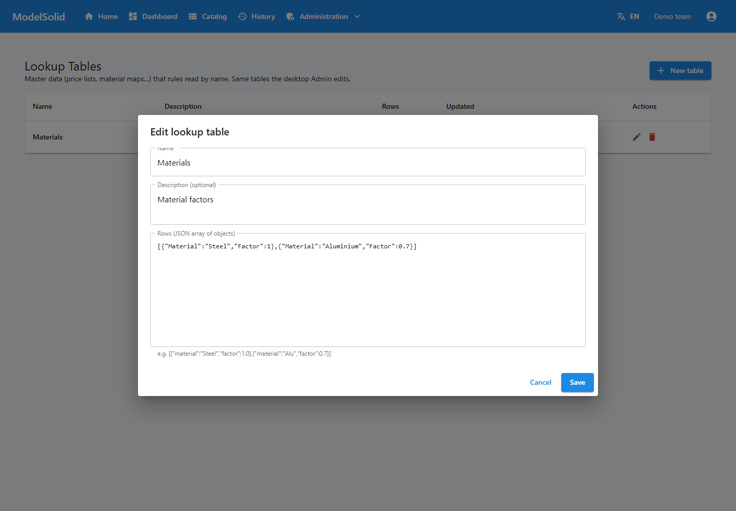
Lookup table editor with rows in JSON format. Portal screenshot with demonstration data. Click to enlarge.
18.1 Creating data
- Open Lookup tables.
- Click New table.
- Enter a name and description.
- Enter rows as a JSON array.
- Save and reopen to verify.
Learning example:
[
  { "material": "Steel", "factor": 1.0 },
  { "material": "Aluminium", "factor": 0.7 }
]
Use double quotes for names and text. Numbers use a decimal point and no quotes. The outer structure is a list enclosed in square brackets.
Materials table and its example JSON rows. Demonstration data. Click to enlarge.
18.2 Rule integration
Creating a table does not add form fields or prove that its rows are available in every evaluation. The integration supplying that data to calculations must be prepared and tested.
The engine's LOOKUP helper receives a dictionary; it does not automatically query a persisted table using only its name. Verify integration before using it to determine prices or selections.
Before renaming or deleting tables, identify their consumers.
Materials table and its example JSON rows. Related portal view; it does not show this step being performed in the desktop application, CAD or terminal. Demonstration data. Click to enlarge.
19. Worker and Autopilot
19.1 Operation
The worker queries the API, reserves a job, retrieves data, prepares outputs, uses SOLIDWORKS and reports success or failure.
It sends activity signals during execution. The API controls the reservation and attempt so that another execution's completion cannot simply overwrite its state.
Web monitor of jobs and their statuses. Demonstration data. Click to enlarge.
19.2 Operational checks
Check that the Windows session is signed in, the task is running, the API is reachable and file permissions are correct.
Plan concurrency around the processes and licences actually available. A SOLIDWORKS instance should not be used to process models in parallel without coordination.
Web monitor of jobs and their statuses. Demonstration data. Click to enlarge.
19.3 Autopilot Settings
In desktop Admin, Autopilot Settings displays status and actions such as installing, starting, stopping, restarting or uninstalling the worker task.
These may require elevation and affect local processes. Check running jobs and open documents before stopping or restarting.
This section is desktop-only because it controls Windows, not just API data.
Web monitor of jobs and their statuses. Related portal view; it does not show this step being performed in the desktop application, CAD or terminal. Demonstration data. Click to enlarge.
19.4 Settings limitation
The screen shows pool size, timeout, retries, version and automatic restart. In this revision, saving writes preferences to %APPDATA%\ModelSolid\autopilot-settings.json; no use of this file by the worker was found.
Saving these fields does not demonstrate that effective concurrency or timeout changes. The technical administrator must review the configuration consumed by the process and verify its logs.
Web monitor of jobs and their statuses. Related portal view; it does not show this step being performed in the desktop application, CAD or terminal. Demonstration data. Click to enlarge.
19.5 When jobs are not processed
Check API, task and session, authentication, and access to SOLIDWORKS and files, in that order.
The worker renews its session, but an invalid password, an account without access or an unreachable API requires correcting the cause.
Code, diagnostic and retry action for a failed request. Demonstration data. Click to enlarge.
19.6 Simulation
A simulated mode exists for testing. It can complete workflows without producing real CAD geometry. Verify that a deliverables workstation uses the real service.
Details and results of a demonstration request. Related portal view; it does not show this step being performed in the desktop application, CAD or terminal. Demonstration data. Click to enlarge.
Web job monitor. Autopilot Settings is managed in the desktop application. Portal screenshot with demonstration data. Click to enlarge.
20. Complete tutorial: configurable plate
The goal is to produce a rectangular plate from the portal. Use a test project and a master prepared by engineering.
Demonstration plate result: inputs, calculated area and documents. This does not verify real CAD generation. Portal screenshot with demonstration data. Click to enlarge.
Step 1. Define the product
Inputs: width, height and thickness. Initial case: 300 × 200 × 8 mm.
Learning limits: width 100–600, height 100–400 and thickness 3–20 mm. Check that your master supports these values before using them.
Start without holes, replacements or prices to validate the basic workflow.
Project identification and settings. Demonstration data. Click to enlarge.
Step 2. Prepare the part
Create or prepare the rectangular sketch and extrusion. Save, manually change the dimensions and rebuild.
Record the actual names. We will assume D1@Profile, D2@Profile and D1@Extrude. If your model uses different names, use yours.
Master path and project output options in the web application. Related portal view; it does not show this step being performed in the desktop application, CAD or terminal. Demonstration data. Click to enlarge.
Step 3. Create and capture
Create a project with a recognisable code and a path accessible to the worker.
In Capture, sign in, select the project and add the master. Check the path, capture the three dimensions and verify mm.
Features registered by Capture, viewed from the web application. Related portal view; it does not show this step being performed in the desktop application, CAD or terminal. Demonstration data. Click to enlarge.
Step 4. Create inputs
| Name | Label | Type | Initial value |
|---|---|---|---|
| Width | Width (mm) | Decimal | 300 |
| Height | Height (mm) | Decimal | 200 |
| Thickness | Thickness (mm) | Decimal | 8 |
Leave their expressions empty and save. Optionally add Area with Width * Height: the initial values should produce 60000 mm².
Variable creation dialog in the portal. Demonstration data. Click to enlarge.
Step 5. Connect dimensions
| Example dimension | Expression |
|---|---|
| D1@Profile | Width |
| D2@Profile | Height |
| D1@Extrude | Thickness |
In Model Rules, save and click Test all. Expect 300, 200 and 8.
Input variables and expression for the derived Area variable. Related portal view; it does not show this step being performed in the desktop application, CAD or terminal. Demonstration data. Click to enlarge.
Step 6. Configure outputs
Enable part and STEP. Do not request assembly or drawing until their masters are prepared.
To test documents, activate a datasheet and review the project's selection.
Master path and project output options in the web application. Demonstration data. Click to enlarge.
Step 7. Prepare the form
Follow chapter 12. Associate modelsolid.json with the GUID, adapt the example, fetch types, review the design, build and upload.
Pay particular attention to the names and capitalisation of Width, Height and Thickness.
Example form with request inputs and options. Demonstration data. Click to enlarge.
Step 8. Publish
Publish from Published Apps or web administration. Open the catalog and form.
If the configurator is pending, check the bundle. Uploading and publishing are separate steps.
Web project list and publication status. Demonstration data. Click to enlarge.
Step 9. Request a variant
Using a test account with Catalog and History access, request 350 × 250 × 10 mm, part and STEP.
Keep the code and track the instance. If Error appears, correct the cause before retrying.
Example form with request inputs and options. Demonstration data. Click to enlarge.
Step 10. Inspect
Open the part from the output folder and check all three dimensions. Open STEP and confirm that it belongs to that instance.
If you added Area, it should be 87500 mm². Also check the datasheet if requested.
Details and results of a demonstration request. Related portal view; it does not show this step being performed in the desktop application, CAD or terminal. Demonstration data. Click to enlarge.
Step 11. Extend testing
Test minimum, maximum and intermediate values. Enter an invalid value and check the form message. Review server validation if data arrives through another route.
Then add options, properties, drawings or replacements one at a time. This makes it easier to identify the source of failures.
History for locating the request by code and status. Demonstration data. Click to enlarge.
Completion criterion
The project is ready when a normal account can open it, submit different values, obtain the corresponding geometry and access the intended results.
Keep the values and results of this test for comparison after future changes.
Details and results of a demonstration request. Related portal view; it does not show this step being performed in the desktop application, CAD or terminal. Demonstration data. Click to enlarge.
21. Maintenance and changes
21.1 Daily review
Check API, worker, recent failures, free space and repeated reference or export warnings. Keep a small known project to verify a workstation after maintenance.
Web monitor of jobs and their statuses. Demonstration data. Click to enlarge.
21.2 Changing a master
Keep the working version. Modify and rebuild, review captures and rules, and generate representative cases.
Remember that capturing all dimensions does not remove old records.
Master path and project output options in the web application. Related portal view; it does not show this step being performed in the desktop application, CAD or terminal. Demonstration data. Click to enlarge.
21.3 Changing variables
Identify dependencies, save, update types, adapt the form, then build and upload again. Renaming requires reviewing references, not just labels.
Input variables and expression for the derived Area variable. Demonstration data. Click to enlarge.
21.4 Required backups
| Item | Reason |
|---|---|
| Database | Projects, captures, users and instances |
| Masters and dependencies | Starting geometry |
| Form sources | Ability to rebuild forms |
| Published bundles | Served forms |
| Outputs and documents | Existing deliverables |
| Configuration | Paths and connections |
The database does not contain every file. Coordinate consistent backups and test restores in a separate environment.
Workspace details and configured path. Related portal view; it does not show this step being performed in the desktop application, CAD or terminal. Demonstration data. Click to enlarge.
21.5 Updating the installation
Coordinate API and worker updates, especially if the job protocol changes. See the September 2026 corrections.
The technical administrator must handle SQLite and PostgreSQL migrations separately. Portal users do not need to run migrations to submit requests.
Portal sign-in screen. Related portal view; it does not show this step being performed in the desktop application, CAD or terminal. Demonstration data. Click to enlarge.
Workspace details and path: information to review when maintaining the installation. Portal screenshot with demonstration data. Click to enlarge.
22. Troubleshooting
| Symptom | Check | Action |
|---|---|---|
| Portal will not open | Address and API | Confirm URL and availability |
| Only Home appears | Groups | Assign pages and reload |
| No Catalog | catalog permission | Review groups |
| Product does not appear | Project status | Publish and reload |
| Configurator pending | Bundle | Upload to the correct GUID |
| Blank form | Bundle resources | Review browser errors and rebuild |
| Generate in Vite creates no request | Preview mode | Submit from the portal |
| CLI returns 401 | Session and URL | Sign in to that API |
| CLI returns 403 | Role | Use an authorised Admin account |
| Rule cannot find a variable | Name, type and saved state | Correct references |
| Test all uses previous data | Unsaved edit | Save first |
| Form changes but part does not | Dimension mapping | Review submission and rules |
| Incorrect scale | Units | Check mm/deg and duplicate conversions |
| Holes disappear when enabled | Boolean suppression | true means suppress |
| Remains Submitted | Worker and queue | Check task, session, API and load |
| Remains Generating | Activity and SOLIDWORKS | Review logs and dialogs |
| File not found | Path as seen by worker | Correct location and dependencies |
| Missing STEP or CAD PDF | Format and source | Review request, captures and logs |
| No datasheet | Templates | Review activation and selection |
| Unchecking templates generates all | Empty selection | Empty removes the restriction |
| Direct download returns 401 | Missing authentication | Use the application's button |
| User cannot see others' requests | Ownership | Expected behaviour |
| Admin changes disappear | Concurrent edits | Coordinate and refresh |
| Changing pool has no effect | Local preferences | Review effective configuration |
Example failed request: retain the code and diagnostic before correcting the cause and retrying. Portal screenshot with demonstration data. Click to enlarge.
22.1 Investigating a failure
Record code, project, time and error. Determine whether the problem affects one set of values, one project or all projects.
For one project, review master, references, rules and outputs. If all fail, start with API, worker session, authentication, SOLIDWORKS and folders.
Keep the instance and logs until the issue is resolved and compare them with a retry.
Code, diagnostic and retry action for a failed request. Demonstration data. Click to enlarge.
22.2 Finding logs
The add-in writes %TEMP%\modelsolid-swaddin.log. API and worker logs depend on storage settings; check Logs under the installation root when using the standard configuration.
Check date, time and process so you do not mistake an old log for the latest startup.
Code, diagnostic and retry action for a failed request. Related portal view; it does not show this step being performed in the desktop application, CAD or terminal. Demonstration data. Click to enlarge.
22.3 Reporting an issue
Include code, project, date and time, submitted values, expected result, message and reproduction steps. Images should show the error and necessary context.
Do not attach passwords, tokens or session files.
Code, diagnostic and retry action for a failed request. Demonstration data. Click to enlarge.
23. Checklists
23.1 Before publishing
- Masters and dependencies accessible to the worker.
- Captures match the current model.
- Correct units.
- Consistent variables and types.
- Rules saved and tested.
- Boolean suppression checked.
- Exact names in the form.
- Bundle built and uploaded to the correct project.
- Outputs possible with the existing masters.
- Templates produce correct content.
- Workflow validated using User.
- Real files inspected for a different variant.
- Copy of the working version retained.
Templates selected to generate project documents. Demonstration data. Click to enlarge.
23.2 Before submitting
- Correct product.
- Correct dimensions and units.
- Options and formats reviewed.
- No equivalent request already pending.
- Confirmation received and code retained.
Example form with request inputs and options. Demonstration data. Click to enlarge.
23.3 Before using deliverables
- Instance finished and errors reviewed.
- Files belong to the correct code.
- Requested dimensions.
- Correct components and optional features.
- Drawing corresponds to the generated model.
- Document data and units checked.
Details and results of a demonstration request. Demonstration data. Click to enlarge.
23.4 After updating
- API uses the correct database.
- Portal, desktop and Capture connect.
- Worker authenticates and processes jobs.
- Reference project generates correctly.
- User permissions checked.
- Document downloads available.
Web monitor of jobs and their statuses. Demonstration data. Click to enlarge.
Reviewing active templates as part of the pre-publication checks. Portal screenshot with demonstration data. Click to enlarge.
24. Frequently asked questions
Does a salesperson need to program?
No. They use a prepared form. Programming rules and designing the form are the author's responsibilities.
Do they need SOLIDWORKS installed?
Not for the portal. The workstation generating real CAD does need it.
Does adding variables create the form?
No. Data and interface are prepared separately.
Can I close the browser?
Yes, after submission is confirmed. The generation workstation must keep running.
Does publishing generate files?
No. It makes the project available. Files are produced when requests are processed.
Does push publish the project?
It uploads the bundle. Publication status is managed separately.
Does testing a rule validate geometry?
No. Generate and inspect the result.
Why do old captures remain?
Bulk capture adds records. Check configurations and hidden dimensions before removing obsolete records.
Why does unchecking all templates still generate documents?
An empty selection means all active templates.
Can I speed up generation by changing the pool in Autopilot?
Local preferences do not demonstrate an effective process change. The actual configuration needs sufficient resources and licences.
Does retrying change the inputs?
No. Create another instance for different values.
Can all CAD files be downloaded from the detail screen?
The reviewed screen downloads PDF/DOCX documents. The administrator should organise access to CAD outputs.
Are spreadsheets used for rules?
No. Rules use C# expressions, data uses JSON or CSV where applicable, and documents use PDF/DOCX.
Does the Material property change density?
Do not assume so. A text property and a physical material are different concepts.
User catalog: published products provide access to their forms. Portal screenshot with demonstration data. Click to enlarge.
25. Glossary
| Term | Meaning |
|---|---|
| Add-in | Extension integrated into SOLIDWORKS |
| Alias | Name of a capture |
| API | Central service |
| Autopilot | Local generation control area |
| BOM | Bill of materials or components |
| Bundle | Compiled form |
| Capture | Recording model elements |
| CLI | Command-line tool |
| Dimension | Measurement controlling geometry |
| Custom property | User-defined property |
| Derived variable | Calculated variable |
| Drawing | Technical drawing |
| Feature | Model operation |
| GUID | Technical identifier |
| Instance | Specific request |
| Job | Processing work item |
| Master | Starting model |
| Publish | Offer a project in the catalog |
| Rule | Calculation expression |
| Roslyn | C# evaluation technology |
| Suppression | Disabling a feature |
| Replacement token | Component selection name |
| Worker | Generation process |
| Workspace | Project organisation |
Visual example of an input, derived variable and expression, terms used in the glossary. Portal screenshot with demonstration data. Click to enlarge.
26. Installation details and support
Your administrator supplies the portal URL, model locations and access to output files. The manual is also available from Home in your installed portal.
For support, record the project and instance code, time, inputs and the exact error. Do not send passwords, session tokens or confidential customer models.
Contact: info@modelsolid.com.
SOLIDWORKS® is a trademark of Dassault Systèmes. ModelSolid is not affiliated with or endorsed by the trademark owner.
Portal home: access to the manual and installation sections.